Flexible and Rigid-Flex boards offer many different connection capabilities than standard PCBs which can greatly help to reduce packaging requirements. Other benefits include weight reduction, higher signal speeds, increased reliability in high vibration or harsh environments and reduced cost opportunities. These features help electronics designers solve design issues that would be presented with a standard rigid PCB.
One of the biggest advantages of Flexible and Rigid-Flex boards is they circuits can be designed to fit the available space rather than having to design the size of the product to fit the PCBs.
Detailed below are some of the main advantages of why engineers choose Flexible and Rigid-Flex boards.
Condensed packing requirements, packaging size
Increased reliability
Reduced weight
High-Speed signal performance
Resistant to harsh environments
Lower cost
Connector and component and compatibility
Design Considerations
Corners with flexible bending areas
Acceptable Design

Acceptable Design
Unacceptable

Staggered track positioning from layer to layer
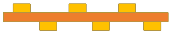
Staggering the track placement on each layer eliminates the "I-Beam" effect that improves the flexibility and reliability of the circuit.
Avoid vias in bending arears
It is not recommended that vias are placed in areas of the boards that will bent as this will add stress and can cause breakages.
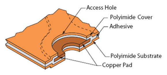
Stiffener termination and Coverlays
Proper reinforcements and roofing terminations prevent significant areas of stress with the flex circuit.
Different types of Flex circuits
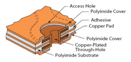
Single Sided Flex
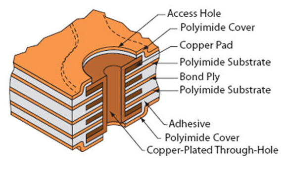
Double Sided Flex
Multi-layer Flex
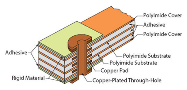
Rigid-Flex
Common Flex material Stack-Up
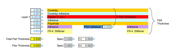
Single layer Flex PCB with optional FR-4 stiffeners and PSA
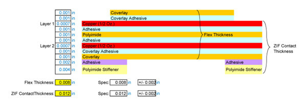
Flexible 2 layer circuit with ZIF contact fingers
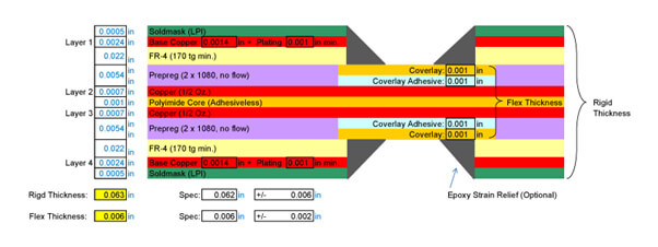
4 Layer Flexible Rigid PCB (2 Flexible Layers)
Date : 05-01-2022
Sign up to receive a monthly PCB newsletter containing the latest information in the world of PCBS including new technology and supply chain information.
Sign up Now
Daleba can manufacture PCBs ranging from single-sided to complex boards in excess of 40x layers. Our in-house CAM engineering resource allows us to rapidly check, panelise and commercially optimise a fast turnaround prototype as well as small volumes. We can supply simple technology boards in as little as 24 hours!


